
Haptick, Part One
Prototyping a tactile input device using a force sensor with six degrees of freedom
In 1983, a student at the University of Sydney named John Hilton started development of a new type of input device for computer aided design (CAD) software. His research led to a technology that allowed intuitive control of virtual objects with a full six degrees of freedom (6DOF). To achieve this, the user would push, pull and twist a small ball, and these manipulations would be applied to the virtual object.
Since then, there have been many embodiments of the concept in a multitude of devices. Collectively they’ve been coined Spacemice, and I want to design and build one.
The Status Quo
The original design used an optical measurement technique to decompose inputs into their constituent orthogonal components — linear motion in the up/down, left/right and forward/backward directions, as well as pitch, roll and yaw rotations1. Throughout the tumultuous commercial history of Spacemice, the technology has been bought, patented, refined, reworked and rediscovered. From my limited research, though, most devices still use optical sensing.
YouTuber Thought Bomb Design has a great video showing a teardown of a SpaceMouse Compact, which clearly illustrates how it works. The knob floats on three springs, which allows it to move and rotate in any direction. Attached to the knob are three posts arranged in a triangle, with a horizontal and a vertical slit through each post. Each slit allows light from an infrared LED fixed to the base to illuminate a differential photodetector mounted to the other side of the base. As the knob is moved or rotated, the light passing through a slit may be swept across the corresponding differential photodetector.
Each differential photodetector measures the position of the light spot that is swept across it. Looking closely at the orientation of the LEDs, slits and photodetectors, we can see that the horizontal and vertical displacement of each of the three posts attached to the knob can be determined. As the three posts form the vertices of a triangle, the displacement and rotation of the triangle (and thus the knob) can be calculated from the measured horizontal and vertical displacements.
It’s a clever, simple and very sensitive method of measuring the rotation and linear displacement of the knob. It could probably be made even simpler by using four quadrant photodiodes like the K857PE, which can measure the position of a light spot in both the horizontal and vertical directions simultaneously. The improved design would need only three photodetectors, three LEDs and a single small hole instead of two slits in each post. I had some other ideas, though…
Other Ideas
I could design and build a similar device that uses optical sensing, but I’ve had a few alternative ideas that I’d like to try out:
- Measuring torques and forces via strain measurements on a load cell.
- Making the 6DOF force/torque sensor from printed circuit boards.
- Using thick-film resistors as strain gauges.
The aim is to be able to build a simple input device that can be assembled by an electronics hobbyist, and hopefully to learn a few things along the way. I’m calling the project Haptick, and, assuming it works, I plan on releasing the design as open-source hardware, firmware and software.
A Geometric Problem
The problem of measuring torques and forces in three dimensions using load cells is primarily a geometric one. How do we position, orient and couple the load cells so readings from them can be related back to orthogonal components of the force and torque? We know we need at least six load cells, as we have six unknowns - $x$, $y$ and $z$ components of force, and $x$, $y$ and $z$ components of torque.
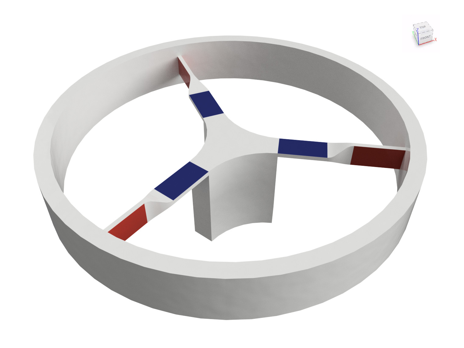
My first idea was to use three arms fixed to a central point within the knob. Each arm would have two load cells on it, one to measure horizontal and one to measure vertical bending moments. The image to the right illustrates this, with the red load cells measuring horizontal deflection and the blue measuring vertical deflection. The blue load cells would give great responses for force along the $z$ axis, as well as torques about the $x$ and $y$ axes. The red load cells would be sensitive to torques about the $z$ axis, but I wasn’t confident they’d work well for horizontal forces in the $x$ and $y$ directions.
The reason for this was because the structure would be stiff under any horizontal forces. The geometry would mean that for any horizontal force aligned with an arm, the arm would have to stretch/compress to be able to induce any bending in the other two red load cells. In an attempt to solve this problem, I dove down a rabbit hole of flexure and compliant mechanism design. There is some really innovative stuff out there in the literature, but nothing seemed practical to fabricate in a small area on a circuit board. During my search, however, I did notice one geometry continuously referenced in relation to 6DOF motion designs — the Stewart platform.
The Stewart Platform
A Stewart platform is a particular geometry of six linear actuators and universal joints that allows a platform to be moved with a full six degrees of freedom. It was originally developed to move replica cockpits in flight simulators using hydraulic actuators. Today the geometry finds application in many places where short throw, mechanically simple 6DOF motion is needed, including micropositioning stages and actively stabilised platforms.
The kinematics of a Stewart platform are unusual. Calculating the actuator length from a known platform position and orientation (inverse kinematics) is simple trigonometry. Calculating the position and orientation of the platform from known actuator lengths (forward kinematics) is much more complex. Indeed, solutions for a general geometry with planar universal joints only started appearing around 19942, some 30 years after the original paper by Stewart3 (which itself was around 15 years after the geometry was developed by an engineer at Dunlop named Eric Gough).
As well as equations of motion, there are also a set of equations to calculate the force and torque on the platform from the compression/tension forces in each truss. Fortunately for me, the math gets a lot simpler if the platform and trusses have a known, static geometry. As published by Fichter4 and Merlet5, the analysis is essentially a force and moment balance ($\sum \bm{F} = 0$ and $\sum \bm{M} = 0$).
Each truss is connected to the platform via a universal joint, meaning each truss can only apply a force to the platform in the direction of the truss. Let’s denote:
- the force and torque vectors applied to the platform as $\bm{F}_p$ and $\bm{M}_p$ respectively,
- the index of each truss as $i$,
- the unit vectors representing the direction of each truss as $\hat{\bm{u}}_i$,
- the forces each truss applies on the platform as $F_i$, and
- the location vectors of the platform universal joints each truss attaches to as $\bm{p}_i$.
The force balance then becomes:
$$ \sum_{i=1}^6 F_i \hat{\bm{u}}_i = -\bm{F}_p $$And the moment balance then becomes:
$$ \sum_{i=1}^6 F_i (\hat{\bm{u}}_i \times \bm{p}_i) = -\bm{M}_p $$We expand these out, and decompose the vectors into their constituent $x$, $y$ and $z$ components. Component $j$ of vector $\bm{v}$ is denoted as $\lang \bm{v} \rang_j$. This results in a big matrix equation to solve:
$$ \begin{bmatrix} \lang\hat{\bm{u}}_1\rang_x & \lang\hat{\bm{u}}_2\rang_x & \lang\hat{\bm{u}}_3\rang_x & \lang\hat{\bm{u}}_4\rang_x & \lang\hat{\bm{u}}_5\rang_x & \lang\hat{\bm{u}}_6\rang_x \\ \lang\hat{\bm{u}}_1\rang_y & \lang\hat{\bm{u}}_2\rang_y & \lang\hat{\bm{u}}_3\rang_y & \lang\hat{\bm{u}}_4\rang_y & \lang\hat{\bm{u}}_5\rang_y & \lang\hat{\bm{u}}_6\rang_y \\ \lang\hat{\bm{u}}_1\rang_z & \lang\hat{\bm{u}}_2\rang_z & \lang\hat{\bm{u}}_3\rang_z & \lang\hat{\bm{u}}_4\rang_z & \lang\hat{\bm{u}}_5\rang_z & \lang\hat{\bm{u}}_6\rang_z \\ \lang\hat{\bm{u}}_1 \times \bm{p}_1\rang_x & \lang\hat{\bm{u}}_2 \times \bm{p}_2\rang_x & \lang\hat{\bm{u}}_3 \times \bm{p}_3\rang_x & \lang\hat{\bm{u}}_4 \times \bm{p}_4\rang_x & \lang\hat{\bm{u}}_5 \times \bm{p}_5\rang_x & \lang\hat{\bm{u}}_6 \times \bm{p}_6\rang_x \\ \lang\hat{\bm{u}}_1 \times \bm{p}_1\rang_y & \lang\hat{\bm{u}}_2 \times \bm{p}_2\rang_y & \lang\hat{\bm{u}}_3 \times \bm{p}_3\rang_y & \lang\hat{\bm{u}}_4 \times \bm{p}_4\rang_y & \lang\hat{\bm{u}}_5 \times \bm{p}_5\rang_y & \lang\hat{\bm{u}}_6 \times \bm{p}_6\rang_y \\ \lang\hat{\bm{u}}_1 \times \bm{p}_1\rang_z & \lang\hat{\bm{u}}_2 \times \bm{p}_2\rang_z & \lang\hat{\bm{u}}_3 \times \bm{p}_3\rang_z & \lang\hat{\bm{u}}_4 \times \bm{p}_4\rang_z & \lang\hat{\bm{u}}_5 \times \bm{p}_5\rang_z & \lang\hat{\bm{u}}_6 \times \bm{p}_6\rang_z \end{bmatrix} \begin{bmatrix} F_1 \\ F_2 \\ F_3 \\ F_4 \\ F_5 \\ F_6 \end{bmatrix} = \begin{bmatrix} -\lang\bm{F}_p\rang_x \\ -\lang\bm{F}_p\rang_y \\ -\lang\bm{F}_p\rang_z \\ -\lang\bm{M}_p\rang_x \\ -\lang\bm{M}_p\rang_y \\ -\lang\bm{M}_p\rang_z \end{bmatrix} $$The 6×6 matrix on the left can be precalculated from the static platform and truss geometry. The result is a simple relationship between the amplitude of the forces in the trusses and the three components of the force and three components of the torque exerted on the platform.
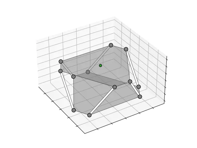
To better visualise the relationship, I generated the animations above and below that show the forces in each truss when a force or torque is applied to the platform. The darker the orange, the higher the compression, the darker the blue, the higher the tension. The green arrow indicates the direction and magnitude of the applied force or torque.
I spent a bit of time optimising the geometry to ensure the induced truss forces were similar in magnitude for both applied forces and applied torques. For an input device, I estimated applied forces to be < 1 N and applied torques to be < 0.03 N.m. After these calculations, simulations and optimisation, I was fairly confident that the Stewart platform geometry could be used in a 6DOF force/torque sensor. The next challenge was the mechanical and electronics design itself.
Starting With a Prototype
Designing a small, static Stewart platform with built-in load cells required a bit of thought. I wanted to make the design simple and cheap enough to be accessible to hobbyists, which led to some ideas I wasn’t certain would work. It made sense to start with a proof-of-concept I could use to test these ideas and iterate further.
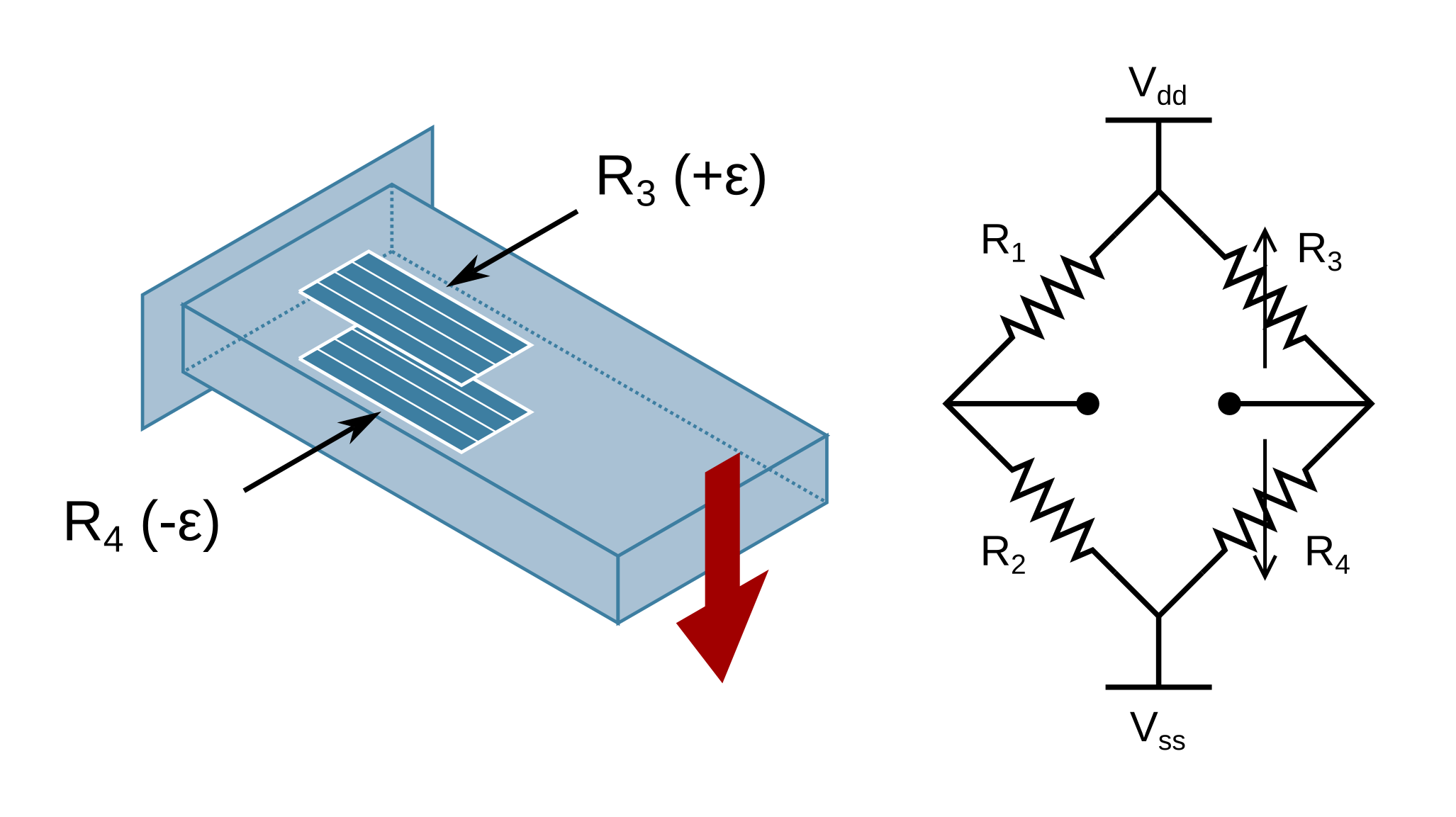
To measure forces in the trusses, I decided to use simple cantilever load cells with strain gauges mounted to the top and bottom in a half bridge configuration. This is the classic bending load cell example you see in textbooks. I’ll use one at the bottom of each of the six trusses to measure the vertical ($z$) component of the force in each truss.
The required universal joints presented a problem. The smallest available parts I found were ball joints for tie rods on remote controlled vehicles, which seemed a little chunky and difficult to mount. Instead of going with mechanical joints, I chose to limit the torque applied through the joint by making the trusses out of a weaker, bendable material. I went with regular 2.5 mm² copper wire, as it is annealed, easy to bend and can be soldered. If the torsion across the joint is still a problem, I have the option of thinning and further weakening the truss at the joint point.
Printed Circuit Board Mechanics
Printed circuit boards (PCBs) are generally associated with electronics, but they are also an attractive option for mechanical parts. With fab houses like JLCPCB and PCBWay, I can get parts precision milled and drilled from fibreglass panel for the price of a few cups of coffee. There is a huge range of fixings and fasteners available, including standoffs, self-broaching nuts, rubber feet and rails. I can make any part of the surface solderable, print graphics on it and ultimately integrate my circuit onto the parts.
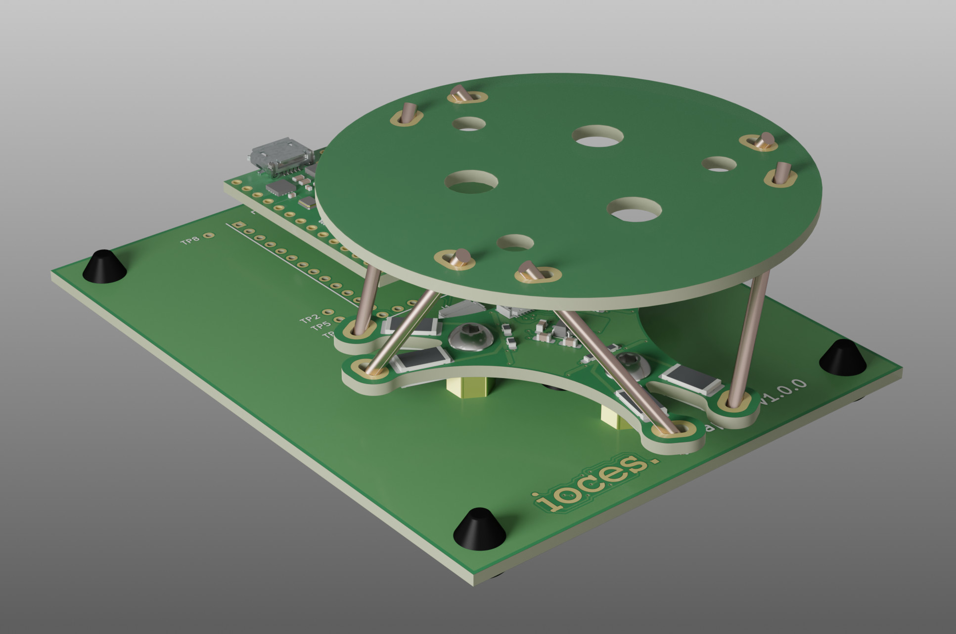
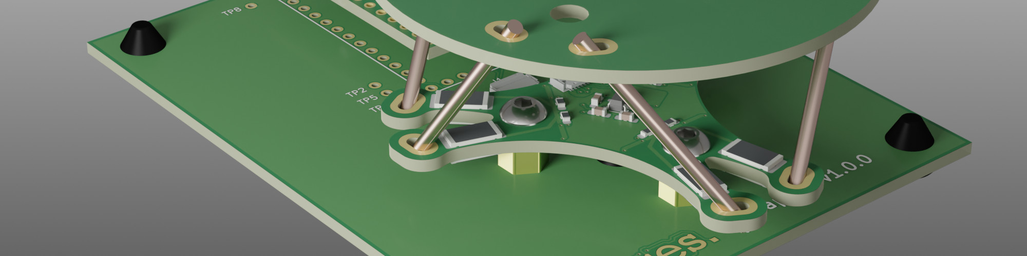
The above rendering shows a general overview of the initial prototype mechanics. It consists of three custom PCBs — the round platform at the top, the load cell board with six integrated load cells and a base that allows everything to sit nicely on a desk. Both the load cell board and the base hold a nominal amount of electronics. The load cell board holds the interface to the strain gauges, and the base integrates a microcontroller that sits between the load cells and the computer.
The six bending beam load cells are formed as a part of the PCB outline. There will almost certainly be problems with plastic deformation and hysteresis in the FR-4 fibreglass, but I’d like to test it and see how well the PCB load cells work. At the end of each of the bending beams, plated slots are used to allow soldering of the trusses directly to the ends of the beams. The same slots are used in the top platform which will allow the platform to be soldered into place.
Everything else is held together using regular standoffs, self-broaching nuts and button head screws. The whole assembly sits on rubber feet for stability. I will probably bust out the 3D printer to print a big knob that mounts to the top platform, but I’ve managed to build up a lot of the mechanics with just plain old PCBs.
Surface Mount Strain Gauges
The observant amongst you will have noticed that the strain gauges mounted to the bending beam load cells look awfully like surface mount resistors. In fact, they are, and they have been used successfully for similar applications before. lvDm has a design for a touch probe based on this technique, and Duet 3D uses something similar in v3.0 of their smart effector. The literature on the effectiveness of thick-film resistors as strain gauges confirms their sensitivity. Canali et al.6 claim “The relative change in resistance of thick-film resistors is linear, reproducible, and hysteresis free for the full range of applied strain.”
Traditional strain gauges are a nuisance to glue in place, and don’t come in surface mount form, hence the attempt to use resistors in their places. Perhaps there is a market in the future for strain gauge manufacturers to do surface mount devices?
The Electronics
Electrically, the sensor is very simple. For the prototype I decided to use an off-the-shelf microcontroller board (a Teensy 3.2) to handle the heavy lifting. It will interface to the load cell board and grab measurements, calculate $x$, $y$ and $z$ forces and torques from the six load cells, and present itself as a USB HID joystick to the connected computer.
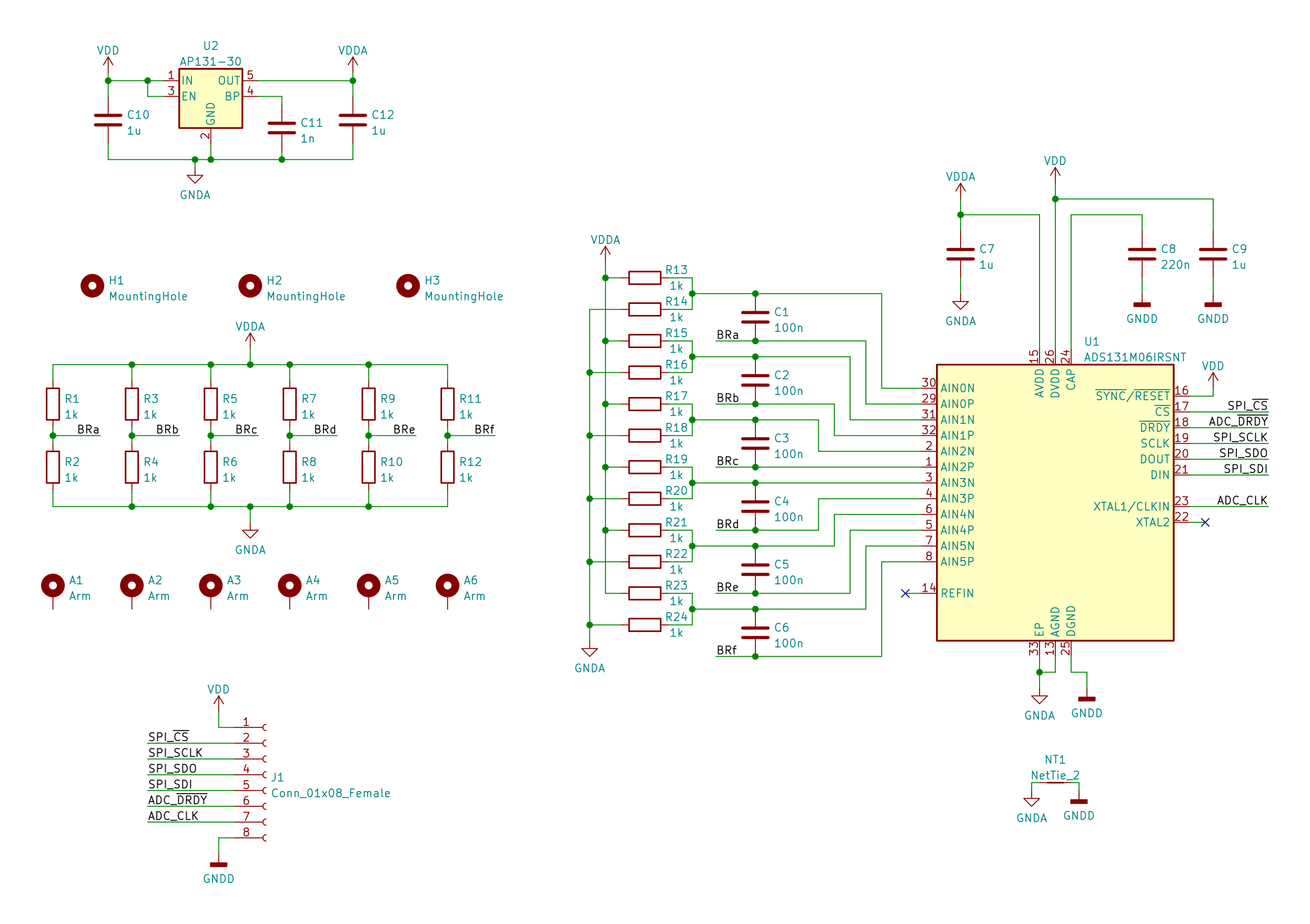
The load cell board is based around the Texas Instruments ADS131M06 analogue to digital converter (ADC). It’s pretty much ideal for this project with 6 differential input channels, simultaneous sampling, built in programmable gain amplifiers (PGAs) and high resolution (24-bit) sigma-delta converters. The interface is mostly standard serial peripheral interface (SPI) with a few extra clocks and interrupt lines thrown in for good measure.
The rest of the board contains a low-dropout (LDO) regulator to generate a nice clean analogue supply voltage, the other halves of the bridges for the load cells and some trivial antialiasing filtering for the ADC.
Schematic capture, placement and routing for all of the boards was done in KiCad, which has had a massive overhaul with the release of v6.0. I was impressed with what I saw. The UI felt fresh, intuitive and crazy fast. The change to s-expression based file formats opens the door to really powerful design rule checking. I feel the same s-expressions would be great to use for filtering and searching. With the pace KiCad development is going at, I’m really looking forward to future releases.
Waiting Game
So where are we now? At this point, I’m waiting on components and PCBs to arrive so I can assemble and test the prototype. If I can get it to work, there is still a lot of effort required to get it into a state where it is useable as an everyday input device. I’ll likely open up the design and see if I can get the open source community to help out. Even if it doesn’t work as anticipated, it’s going to be interesting to see where it falls short. Ultimately this an experiment and a learning experience, and I have no doubt it’ll provide some interesting insights.
Hilton, J. A. and Spatial Systems Pty Limited (1989). Force and torque converter. United States Patent US4811608 ↩︎
Wen, F. and Liang, C. (1994). Displacement analysis of the 6-6 stewart platform mechanisms. Mechanism and Machine Theory, 29(4), pp. 547–557 ↩︎
Stewart, D. (1965). A Platform with Six Degrees of Freedom. Proceedings of the Institution of Mechanical Engineers, 180(1), pp. 371–386 ↩︎
Fichter, E. F. (1986). A Stewart Platform- Based Manipulator: General Theory and Practical Construction. The International Journal of Robotics Research, 5(2), pp. 157–182. ↩︎
Merlet, J.-P. (1987). Parallel manipulators, Part I: Theory - design, kinematics, dynamics and control. Unité de recherche INRIA Sophia Antipolis. ↩︎
Canali, C., Malvasi, D., Morten, B., Prudenziati, M. and Taroni, A. (1980). Strain Sensitivity in Thick-Film Resistors. IEEE Transactions on Components, Hybrids, and Manufacturing Technology, 3(3), pp. 421–423. ↩︎